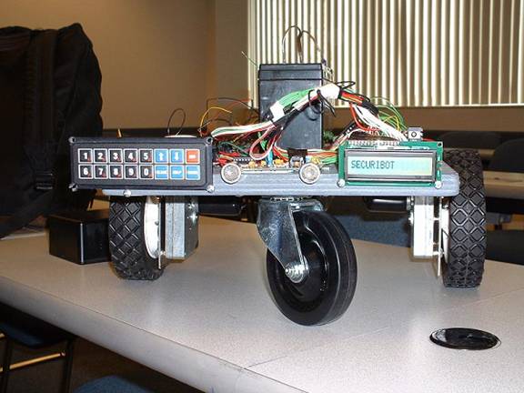
The base of SECURIBOT will be constructed from plywood because it is sturdy, easy to cut to size and is readily available. The group has decided to construct the base in a square-like dimension mainly because it will be easier to mount square circuit boards on a square base thus taking advantage of all of the room on the base. There will be 2 castor wheels used for support and maneuverability. The various circuit boards will be attached to the base using metal standoffs and the battery will be secured with some type of holder, but that still needs to be discussed and the specifics to be decided upon. The sizes of the drive wheels are projected to be 6 inches in diameter. A 6-inch drive wheel should give SECURIBOT a desired travel speed of 1-2 feet per second.
The drive motors(Figure 1) that will allow SECURIBOT to move about were purchased and received on 12/27/2002. They were purchased from Zagros Robotics, but the actual motors are made by Dayton Electric Co. The specifications are as follows:
|
Voltage Rating |
Gear Reduction |
Output Speed |
Torque Rating |
Current Draw (Full Load) |
|
12 Volt DC |
270:1 |
25 rpm |
20 In-lb |
1.30 Amps |
Fig. 1 
To mount these motors to our wooden base “L” brackets will be purchased/fabricated. We intend to use a 12 Volt sealed lead acid battery as the motor’s power source (Figure 2). Even though this type of battery may be a bit on the heavy side they are excellent for supplying the needed current for sustained periods of time and are easy to recharge. The motors selected have no problem handling the weight of the wooden platform, battery, wheels, and various circuit boards.
UPDATE: An adjustable voltage regulator circuit was built with the LM317T regulator IC. 12-volt battery voltage is sent into the regulator and the output voltage is adjusted to 9 volts. That 9 volts is the voltage supply for the rest of the circuits. This was done because the circuitry was using up 9-volt batteries too quickly. This way we won’t have to keep buying batteries.
Fig. 2 
The motors will be driven by an N-channel power MOSFET H bridge circuit that is made up of N-channel MOSFET devices, diodes and inverter logic gates. Each motor will have its own H bridge motor control. The motor control circuits were built on a breadboard, and they will be transferred to a permanent circuit board after interfacing is tested. See schematic. (Appendix)
UPDATE: Instead of using the drive controller that I built earlier I borrowed a motor controller board built by Professor Stewart. It uses two LMD18201T H-Bridge ICs, one for each motor (Figure 3).
Fig. 3 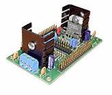
The next step in the construction of the platform, once the “L” brackets have been obtained, is to attach the drive motors and castor wheels along with the drive control electronics. Testing and tweaking of the base will also be done at that point.
SECURIBOT NAVIGATION
It was decided that the type of navigation that will be used is Wall Following. The wall is used to provide the robot with navigation orientation.
Active sensor, non-contact Wall Following using active proximity infrared sensors will be used to determine SECURIBOT’s distance from the wall. No physical contact to the wall is needed and two sets of infrared sensors will be used to judge when SECURIBOT is parallel to the wall (Fig. 4).
UPDATE: The IR sensors used are the SHARP GP2D12 distance rangers. Three of them are used. Two sensors are mounted on the sides of SECURIBOT. These will measure the distance to the wall and the voltage signal will be inputted into the microcontroller. The microcontroller will be programmed so that it will either slow down or speed up a drive motor. When there is no wall SECURIBOT will seek out a wall, in sense it will scale the wall. This process will be done constantly to keep SECURIBOT moving parallel to the wall. An additional IR sensor is mounted to the front of SECURIBOT so that when it reaches the wall or object in front of it, it will turn to the right. It can basically follow the wall all the way around a room. When it gets to an opening like a doorway it will go through it and start seeking walls again.
Fig. 4 
SECURIBOT MICRO CONTROLLER
The OOPic microcontroller ($69.99) was selected on 12/20/2002. The OOPic made by Savage Technologies was chosen because of its ability to be programmed in C/C++. It also has the capability to multitask several operations. In addition, it has a built in analog to digital converter and pulse width modulator, which are features needed in this project. A list of features is listed below.
|
|
|
|
|
|
|
|
|
|
A flowchart of SECURIBOT’s operation is in the appendix. The flowchart shows how SECURIBOT will operate under normal conditions.
The next step is to define in detail all of the blocks in the flowchart, then write and test code for each block.
The microcontroller used to power SECURIBOT is the OOpic firmware version B.1.x manufactured by Savage Innovations (Figure 5). It was selected over competing microcontrollers 8051 and the Basic Stamp because of cost, ease of use, and functionality. The price of the OOPic, programming cable, and power connector is 69.99 - the programming software is free and can be downloaded at OOPic.com. Also, the OOpic can be programmed in C Java, or Basic, and it is object oriented, which mean the functionally of peripheral, such as a DC motor, can be represented by a single variable. Because of this, SECURIBOT's program is easy to read and maintain.
Fig. 5
The OOPic has 31 input/output pins of witch four can be used as an ADC. Three of the ADC pins are connected to the IR Rangers to measure the distance to the wall. Two pins are programmed to be input and are used to monitor the data line coming from the motion detectors. Eight pins are use to interface with the keypad, and 6 pins are used for the LCD. One output pin sends the alarm signal, active low, to the transceiver. The OOPic also has 2 pins which are connected the DC motors to provide pulse width modulation (varying the duty cycle), and 2 pins that control the direction. One ground pin and one 5v pin provides power to the peripherals.
In order to provide more power, the voltage regulator was changed to a TO-220 case version of the 7805 5-Volt regulator, which can supply up to 1 amp of current at 5 Volts (Figure 6). To do this, the original 5-Volt regulator was removed and the new voltage regulator put in it place (Figure 7).
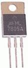 Fig.
6
Fig.
6
 Fig.
7
Fig.
7
Keypad
The keypad is used to start and stop SECURIBOT and depending on the program install it can be use to program the speed and operating mode (Figure 8). The keypad used has a standard 2 x 8 layout with four mounting holes on the corners. The keypad is mounted to the outside of the robot along with the LCD display. Also, the built in object keypad is used to program the keypad.
Fig. 8 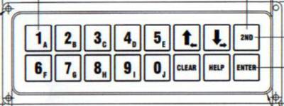
LCD
To monitor the status of SECURIBOT a one-line LCD display is used (Figure 9). LCD module DV-16100-S2FBLY can display up to 16 5 x7 dot characters. It has a built in microcontroller and memory with hold the instructions on displaying ASCII characters. Instructions from the OOPic are feed to the LCD by a 4-bit parallel inputs and outputs. The LCD screen is STN (Super Twisted Nematic) gray transflective and can be illuminated wilt a backlight. The unit is powered by a 5V power supply, which is provided by the OOPic's 5V line.
Fig. 9 
SECURIBOT WIRELESS COMMUNICATION
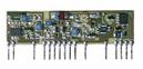
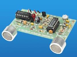
In the wireless communication part of the project, it basically consists of four components: encoder, transmitter, receiver and decoder. The encoder communicates with the transmitter to send a specific signal to the receiver. The receiver communicates with the decoder to decode the signal (which was sent from the transmitter) to give a given output. Below are two diagrams. Figure 10 is an encoder with transmitter and Figure 11 is a receiver with the decoder. Figure 12 is an actual photo. This is a showing of how they communicate with each other.
Fig. 10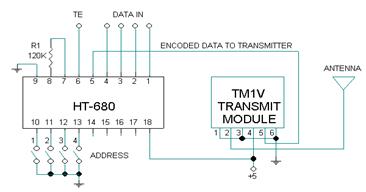
Fig. 11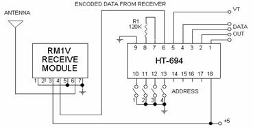
Fig. 12 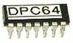
The sensors of the SecuriBot will be activated under their specific application and with interface with the wireless communication part of the project and produce a given output. In the SecuriBot the output will be displayed through LED’s to show which sensor been activated.
The wireless communication for the SecuriBot operated when a motion or fire sensor is activated and it lights up a stationary led, which is connected to the to receiver, indicating that a sensor or sensors has been activated.
The initial plan for the wireless communication for the SecuriBot changed. First the arrangement was to get the transmitter and receiver from a remote control car. During this process the group discovered that it was too difficult to locate the decoder from the receiver, which was pulled out from the car.
Professor Stewart supplied the team with two transceivers and two decoder/encoders. We had to find out who the manufacture was and see if we can find a schematic for the two transceivers named RTF/L-DATA-SAW and the two decoder/encoder chips. After doing the research and finding out that ABACOM design these products, the team constructed the circuit and it didn’t work. I called the company and found out that I had to purchase two decoder/encoder chips named DPC-64 because the two-decoder/encoder chips, which Professor Stewart gave us, were not compactable with the RTF/L-DATA-SAW transceivers.
With the two new DPC-64 chips, I constructed the circuit according to the schematic, however the given schematic was only designed for one DPC-64 chip and one RTF/L-DATA-SAW transceiver. After talking to the company technician, he told me that the transceivers can be divided to work separately as one transceiver being the transmitter and the other transceiver being the receiver, however he didn’t have a schematic and he didn’t know how to design it. Following this information given to me, I reconstructed the circuit in the schematic and develop the circuit to be compactable to our SecuriBot.
In the development stage, I had to purchase two 8 Mhz crystal oscillators which sends and activate the data pulse at the two DPC-64 encoder/encoder chips allow data to send and receive. I also discovered that I had to ground all ground terminals because they were not internally grounded.
Soon after all these modifications, when a motion or fire sensor is activated the microcontroller will send a signal to the encoder and the transmitter will send a signal to a stationary receiver, which have a range up to 100-500 feet, into the decoder which will activate the light up the led indicating that a sensor or sensors has been activated.
SECURIBOT SENSORS
Fire Detector:
Any fire emits smoke. For that reason, the Light Detection Resistor (LDR) is very useful in case of smoke detection.
In the circuit shown in figure ( ), light is emitted from the LED is facing the LDR. In case of a fire, smoke will obstruct the path of light from the LED to the LDR. This will cause the resistance on the LDR to decrease. Consequently, the voltage at the base of the transistor will decrease. The voltage at the emitter will also decrease.
The low voltage output from the emitter is fed into an inverter, which will cause the output of the inverter to go high.
The high output of the inverter is fed into the audio amplification part of the circuit. The audio amplification section consists of the 555 Timer, 220ohm, 100 and 1-kohm resistors, and a 0.01 micro Farad capacitor. As shown in the figure, the output of the inverter is fed into pin 5 of the 555 Timer, pin 1 is grounded, pins 8 and 4 are connected to the 9v source battery. The output of the Timer, pin 3, is connected to the audio amplifier. The 1 Kohm resistor is responsible for the amplitude of the output sound, while the capacitor is responsible for the frequency.
Difficulties faced:
After building and testing, the circuit was successfully operating. However, the only problem was that the circuit operated in dimmer light environments. This will not be sufficient enough for SECURIBOT, because the alarm might blow in dark rooms for instance.
Overcoming the difficulties:
A box is designed, where the circuit is embedded in it. In that case, the light intensity inside the box will remain constant. Two small holes, one on each side of the box is cut in order to permit the smoke in. Turning off the lights of the room then tests the circuit. It operated successfully. The voltage measurements of the transistor are shown in the following table:
|
|
In case of regular room light |
In case of smoke |
|
Base |
4.1 v |
2.9v |
|
Collector |
8.9v |
8.9v |
|
Emitter |
5.2v |
3.1v |
Motion Detector:
Objects that generate heat also generate infrared radiation and those objects include animals and the human body whose radiation is strongest at a wavelength of
9.4 um. A pyroelectric sensor (PIR325) is used for that reason.
The PIR is made of a crystalline material that generates a surface electric charge when exposed to heat in the form of infrared radiation. When the amount of radiation striking the crystal charges, the amount of charge also changes. The sensor elements are sensitive to radiation over a wide range so a filter window is added to limit incoming radiation to the 8 to 14 um range, which is most sensitive to human body radiation.
The PIR325 sensor has two sensing elements, figure 1.0 (horizontal plain) connected in a voltage-bucking configuration. This arrangement cancels signals caused by vibration, temperature changes and sunlight.
As shown in figure 1.0 (Typical configuration), terminal pin 2 (source) connects through a pull down resistor of about 100K to ground and feeds into a two-stage amplifier. Each of the two cascaded stages has a DC gain of 100 for a total gain of 10,000. The amplifier is typically bandwidth limited to about 1 Hz to reject high frequency noise and is followed by a window comparator that responds to both the positive and negative transitions of the sensor output signal. A well-filtered power source of from 3 to 15 volts should be connected to pin 1 (drain) of the PIR.

Figure 1.0
In figure 1.1 (circuit), the circuit uses a low cost LM324 quad operational amplifier as both a stage amplifier and a window comparator. Amplifiers IC1A and IC1B are the two stage amplifier. IC1C and IC1D form a window comparator that responds to signals about 200 millivolts above and 200 millivolts below Vcc/2. The low current voltage drops across D1 and D2 set this window. Comparator outputs feed through D3 and D4, which pass only the positive transitions into CD4538 CMOS single shot IC2, which feeds into Q1 that drives relay RY1. The R12 and C6 time constant determine how long the relay remains energized after motion is detected. All components can operate on 5 to 12 volts; hence, a 9v battery will be used to be consistent with the fire detector.